专注于SF6气体检测的专业化

SF6 leakage monitoring system modification technical specification
General rules
1.1 Type V has not occurred in the general prescribed amount
1.1.1 This technical specification is applicable to the technical requirements of structure, performance, installation and test of SF6 leakage monitoring system transformation of 500kV switch station of Tingzikou Water Project of Jialing River.
1.1.2 This technical specification sets out minimal technical requirements, does not specify all technical details, and does not fully quote the provisions of relevant standards and specifications. Party B shall provide high-quality products that comply with this specification and industrial standards. At the same time, it must meet the national mandatory standards and norms related to safety and environmental protection and the relevant technical parameters of the project design drawings.
1.1.3 All procedures, specifications and standards involved in the design and manufacture of equipment by Party B must comply with the current new version of national standards. If the standards used in this technical specification are inconsistent with those implemented by Party B, the higher standards shall be applied. If Party B does not raise objections to the provisions of this specification in writing, it means that the equipment provided by Party B fully complies with the requirements of this specification. Any objection, no matter how minor, should be described in detail in the quotation in a special section entitled "Comments on and differences from the Specification".
1.1.4 If there is any inconsistency between the bidding documents provided by Party B, Party A shall determine the inconsistency based on the principle that it is more conducive to equipment installation and operation and project quality.
1.1.5 Party B shall be fully responsible for the hardware equipment (including auxiliary systems and equipment) of SF6 leakage monitoring system of 500kV switch station. The manufacturer of the subcontracted (or purchased) products shall obtain prior approval from Party A.
1.1.6 All costs involved in the patents adopted by the equipment and the imported technology are deemed to have been included in the equipment quotation, and Party B shall guarantee that Party A shall not assume all responsibilities for the patents and intellectual property rights of the equipment.
1.1.7 The technical specification of the equipment shall be confirmed by both the buyer and seller as a technical attachment to the order contract and shall have the same legal effect as the text of the contract.
1.1.8 After signing the Contract, Party A shall have the right to put forward some supplementary requirements arising from changes in the specifications, standards and procedures.
1.1.9 This project adopts the power plant identification coding system. Party B shall provide technical documents (including materials and drawings) and equipment nameplate identification to the equipment level. Party B is fully responsible for the uniqueness, regularity, accuracy, completeness and scalability of the identification code of the power plant. The marking principles and methods shall be provided by Party A.
1.1.10 Matters not mentioned in this technical specification shall be determined by both parties through negotiation.
1.2 Project Overview
1.2.1 SF6 leakage monitoring system of 500kV switching station of Tingzikou, the current equipment adopts the pump detection method to select the detection point on both sides of SF6 equipment near the wall, it is difficult to extract the environmental gas near SF6 switch in a timely and accurate manner, resulting in leakage can not be found; In addition, the GIS room has two entrances before and after, and the original device has no human infrared Settings at the front door and no Settings at the back door. If the staff enters from the back door, the fan can not be opened in time to replace the indoor gas, which is easy to cause the danger of poisoning the staff. At the same time, this set of equipment has been used for many years, and the core components of the product have been aging, coupled with the manufacturer's service can not keep up, the equipment can not work normally.
1.2.2 In order to ensure the safe operation of the equipment and provide safety protection for the personal health of the staff, the SF6 leakage monitoring system of the 500kV switch station is proposed to be reformed, that is, the original online SF6 monitoring and control system is cancelled, and the intelligent SF6 infrared leakage monitoring and alarm system is reformed and installed in the switch station. 1 host +16 monitoring points on the zone display (12 2-in-1 transmitters with infrared remote control: SF6 and oxygen; 4 2-in-1 transmitters: SF6 gas, O2, temperature, humidity) +2 fan controllers +2 sets of human infrared and alarm lights +1 set of voice system
1.2.3 Add a software system, involving the main control room system upgrade problems, the equipment must obtain the computer software copyright registration certificate issued by the National Copyright Administration, add an output module, remote transmission to the main control room monitoring system alarm output (when a GIS room leakage occurs at a certain point, the signal is transmitted to the main control room, the alarm is issued, and the staff can find and deal with it in time); The remote transmission module is added, and the field measurement data is remotely transmitted to the main control room, so that the staff can monitor and check at all times to prevent accidents.
1.3 Construction Schedule
1.3.1 Equipment supply shall be completed 30 days after the contract is signed.
1.3.2 Within 10 days after the completion of equipment supply, complete the wiring, debugging and signal sending monitoring system debugging in the SF6 leakage monitoring system cabinet of 500kV switching station.
1.3.3 After commissioning, it will enter the trial operation phase, which will last for 30 days.
1.3.4 Completion of preliminary acceptance after passing the test run. Acceptance shall be field test acceptance. Party B shall submit acceptance test process documents (test plan and test record) to Party A for review and approval 15 days before the test starts. The acceptance test shall complete the comprehensive test of the function and performance of the domestic water supply system in the production area in accordance with the national standards and technical requirements and confirm that the whole system can operate stably and reliably.
1.3.5 After passing the preliminary acceptance, the equipment warranty period shall be 1 year, calculated from the date of passing the preliminary acceptance.
1.4 Standards and Specifications
1.4.1 The manufacture, acceptance and handover of SF6 leakage monitoring system of 500kV switchstation in Tingzikou are mainly based on national standards, and refer to the standards of the power industry and the relevant international standards of imported equipment companies, and must comply with the relevant safety, environmental protection and other mandatory standards and regulations of China.
1.4.2 The technical standard shall be the version at the time the bid is issued.
1.4.3 The imported equipment shall be in accordance with the corresponding national standards and the standards of the manufacturer (company), but shall not be lower than the national standards of China.
The standards used mainly include, but are not limited to:
GB12358-2006 "General Technical Requirements for Workplace Environmental Gas Detection and Alarm Instrument"
GB8958 "Hypoxic hazardous Operation safety Regulations"
GBZ/T205 "Code for the Protection of Occupational Hazards in Confined Spaces"
GBZ/T 206-2007 "Gas Detection Specification for Direct Reading Instruments in Confined Spaces"
GB11920-89 General technical conditions for centralized control device of electrical part of power station
GB4720-84 Low voltage electrical control equipment
JB616-84 General technical conditions for secondary circuit screen (table) of power system
ANSI 488 Mathematical interface for programmable instruments
Binary logic diagram of ISA-55.2 procedure operation
ISA-55.3 Binary logic diagram of process operations
ISA-55.4 Instrument circuit diagram
NEMA-ICS4 Terminal boards for industrial control equipment and systems
Power System Real-time Data Communication Application Protocol DL476
General Rules for Low-voltage Switchgear and Control Equipment GB/T140148.1
The Twenty-five Key Requirements for the Prevention of Major accidents in Power Production are issued for 2000-9-28
State Grid Biotechnology [2005] 400 article 18 major anti-accident measures of the State grid company
Sichuan Power Regulation [2006] No. 96 Sichuan Electric Power Company anti-accident measures implementation rules 5
Basic technical specification for computer monitoring system of hydropower station DL/T578-95
Other relevant standards, such as ISO, IEC, IEEE and other international standards
1.5 Technical data and information that must be provided during bidding
1.5.1 Party B shall provide technical data one by one according to the items listed in the Technical Schedule of technical specifications. The technical data provided shall be warranty data, which shall be part of the contract. If there is any discrepancy with the technical data required by Party A, it shall also be recorded in the technical deviation table.
1.5.2 Product performance parameters, features and other information to be provided.
1.6 Installation and Commissioning Requirements
1.6.1 Party B shall be responsible for guiding the installation and commissioning of SF6 leakage monitoring system of 500kV switchstation in Tingzikou during the whole process of the contract equipment. Party B shall ensure that there is at least one technician on site to solve on-site installation and commissioning problems, and shall assign technicians with abundant experience and strong technical ability. On-site personnel shall be kept fixed and shall not be replaced without consent of Party A. The installation, commissioning and trial operation of the contract equipment shall be completed and transferred to Party A for operation and management after receiving qualified experience.
1.6.2 In the process of equipment installation and commissioning, any deviation from the requirements caused by the manufacturing quality must be recorded in writing and handled by Party B at its own expense.
1.6.3 Party B shall take the initiative to contact Party A to determine the size and interface of the equipment before the equipment is manufactured. If the equipment fails to meet Party A's requirements during the installation and debugging of the equipment, Party A may unconditionally return the equipment and require Party B to bear all losses.
1.7 Cleaning, painting, packaging, handling, transportation and storage
1.7.1 Cleaning
1.7.1.1 The equipment shall be cleaned before delivery.
1.7.1.2 All debris, such as metal fragments, iron shavings, welding slag, rags and all other foreign objects shall be removed from each component.
1.7.2 Paint
1.7.2.1 Party B shall choose the coating method to prevent the equipment from being corroded during transportation and storage.
1.7.2.2 The outer surface of the equipment shall be sprayed with a layer of glue anticorrosion, and the paint color shall be blue.
1.7.2.3 Party B shall provide a complete description of the anti-corrosion, including the cleaning and coating process and the characteristics of the coatings used.
1.7.3 Flags
1.7.3.1 A metal nameplate made of corrosion-resistant materials shall be installed on the obvious part of the equipment, and the metal nameplate shall at least include the following contents: equipment name, equipment model, rated operating parameters of the equipment, conditions of use of the equipment, net weight of the equipment, name of the equipment manufacturer, date of manufacture, and product number of the manufacturer.
1.7.3.2 The type, size, technical conditions and inspection rules of the metal nameplate of the equipment shall comply with the provisions of GB/T 13306-91 "Product Label".
1.7.3.3 The equipment components provided by the standard party shall be packed in accordance with the national standards and relevant technical conditions, and shall be labeled with the contract number and the name of the main equipment.
1.7.3.4 The following information shall be indicated on both sides of the box for the equipment to be packed:
The contract number; Shipping mark; Port of destination; Consignee code; Equipment name and project number; Case number; Gross/net weight; Overall dimensions; Length × width × height.
1.7.4 Handling, transportation and storage
1.7.4.1 The equipment supplied by Party B shall be loaded, unloaded, transported and stored in accordance with national standards and relevant regulations.
1.7.4.2 The dimensions of parts transported by rail shall not exceed those specified for non-standard external forms.
1.7.4.3 When parts are transported by means other than rail, the weight and volume limits shall be in accordance with the provisions of the mode of transport concerned.
2. Engineering site conditions
2.1 Natural meteorological conditions
The annual average temperature is 16.6℃
Extreme maximum temperature 39.1℃
Extreme minimum temperature -4.6 ° C
The annual average relative humidity is 73%
The average annual rainfall is 995.8mm
The maximum daily rainfall is 204.3mm
The annual average maximum wind speed is 13.2m/s
The intensity of the earthquake was 6 degrees
2.2 External traffic conditions
The site of Tingzikou power station has a special approach road connecting with National Highway 212, about 130km north of Guangyuan City, for the mountain secondary road, local slope steep bend. The power station is about 15km away from Cangxi County and 160km away from Nanchong City in the south. The road is 212 National Highway. The overall road is relatively flat, with some hilly ramps and some Bridges and culverts curved and heavy. Guangyuan City and Nanchong City through the railway, the single weight and size of the mechanical and electrical equipment within the railway transport limits, can be transported by rail to Guangyuan Station or Nanchong station in Sichuan province, and then transferred to road transport, but there is no large lifting equipment at the station. Guangyuan-nanchong Expressway was opened to traffic in April 2012, and Guangnan Expressway has an exit in Cangxi County. The specific traffic conditions shall be examined and judged by Party B.
2.3 Site traffic conditions
The special approach road is connected to National Highway 212, with a length of about 7km. It is arranged on the left bank of the power station. The traffic road network in the work area has been formed, and the equipment can be directly transported to the installation site of the power station equipment by using the existing traffic conditions in the field.
2.4 Power Transmission and Distribution Layout
2.4.1 The 275MW unit of the power plant is connected to the original 15.75kV distribution device by generator-transformer connection. Plant starting and backup power is provided by the system's 10 kV step-down.
2.4.2 Plant power system
High voltage plant power system: 10 KV, three phase, 50Hz.
Low voltage plant power system: 400 V, three phase four wire, 50Hz.
DC control power supply: DC 220 V, from the 220 V battery pack, voltage variation range from 209 V to 242 V.
DC power supply: DC 220V, from 220V battery, voltage variation range from 192V to 248V.
Equipment lighting and maintenance power supply: equipment lighting is powered by a separate 400/230V lighting transformer; The rated voltage of the power supply of the repair socket is 380V, three-phase, 50Hz; Single-phase 220V.
Low voltage AC system adopts neutral direct grounding system, three-phase four-wire system.
2.5 Operating Conditions
Rated system frequency: 50 Hz
System operating voltage: 500 kV
Maximum operating voltage: 525 kV
Connection to other devices: None.
Installation location: indoor installation
3. Technical specifications
This technical specification only puts forward the technical requirements for the design, manufacture and test of SF6 leakage monitoring system in Tingzikou 500kV switch station. Party B shall ensure that the equipment and technical performance indicators provided are superior to the requirements set forth in this technical specification. Party B shall be responsible for on-site cabinet wiring, debugging, signal transmission to the monitoring system debugging. The equipment provided by Party B shall be able to meet the long-term safe, stable and reliable operation under different operating conditions under the conditions specified in this Code.
3.1 General Technical requirements
3.1.1 Overview
1) Unless otherwise stated, all electrical equipment provided by Party B shall be applicable to 50Hz single-phase AC 220V or three-phase AC 380V power supply, or DC 220V power supply.
2) Wiring shall comply with the requirements of the relevant provisions of the GB standard.
3.1.2 Electrical Contact Specifications
The contact shall be suitable for use in the control circuit and shall not exceed its rated current and voltage values. The contacts provided for Party A's use shall be electrically independent, ungrounded dry contacts with the following specifications:
1) Maximum design rated voltage: AC 220V or DC 220V;
2) Continuous working current: AC or DC 2A;
3) Maximum breaking capacity: AC 250V, 2A; Dc inductive load 250V, 0.5A.
3.1.3 Transmitters and sensors
1) Transmitters and sensors should be suitable for physical quantities that need to be accurately measured. Its output should be 4 ~ 20mA (full scale) DC current, load resistance is not less than 750W.
2) Unless otherwise specified, the maximum allowable error at 25 ° C shall not exceed ±0.25% of the full scale, and the error caused by the change of temperature from -20 ° C to 60 ° C shall not exceed ±0.5% of the full scale. The AC output pulsation should not exceed 1%. The calibration adjustment of the device should be 10% of the full scale, and the response time from 0 to 99% should be less than 300ms. There should be electrical isolation between input, output, external power supply and housing grounding. The insulation withstand voltage test value of all sensors shall meet the specified test requirements.
3) Temperature detector (RTD) should be selected platinum type, 0℃, resistance is 100W. The measuring range is 0 ~ 150℃, and the measuring accuracy is ±1℃ in this range.
3.1.4 Buttons
1) All buttons should be heavy-duty oil-proof structure.
2) Contact rating
Maximum design voltage: 500V AC and 250V DC
Maximum continuous current: 10A (AC or DC)
Maximum inductive breaking current: AC 220V, 3A and DC 220V, 1.1A
Maximum inductive closing current: AC 220V, 30A and DC 220V, 15A
3) The button should meet the requirements of the relevant provisions of the GB standard.
3.1.5 Relays
1) Sequence relay
Relays for logic control shall be of heavy duty type. The relay shall be designed and tested in accordance with the relevant provisions of the GB standard. The number of contacts should meet the requirements of logic control and connection with the power station computer monitoring system.
2) Time delay relay
Time delay relays shall be solid state with dust cover and 2 single-pole double-throw contact loops with adjustable time delay. If specified, an instantaneous contact loop shall also be provided.
3.1.6 Indicators
1) Type
The indicator should be of switch plate type, with a suitable colored lamp cover and an integral installation resistor, and the light emitting element of the indicator should be LED. The colored lamp cover should be made of transparent material, which will not become soft because the lamp is heated. It should be possible to replace the indicator light from the front of the screen and provide all the special tools required for replacement. All colored lamp covers shall be interchangeable, and all lamps shall be of the same type and rating.
2) Special requirements
Indicators and optical signals for various occasions shall be selected by Party B and submitted to Party A for approval.
Electromagnetic compatibility
The surge suppression capability (SWC), anti-radio interference (RI) and anti-static interference (ESD) capabilities of the system equipment should meet the requirements of IEC61000-4 "Electromagnetic Compatibility Test and test methods".
3.1.8 Electromagnetic interference protection
The normal operation of the system equipment shall not be affected by electromagnetic interference. If necessary, Party B shall install interference-absorbing components at the input ports of the equipment.
3.2 Special Technical Requirements
3.2.1 Control Objects and Layout
The equipment parameters of SF6 leakage monitoring system of 500kV switching station of Tingzikou, Jialing River are as follows:
Serial number | Product equipment name | unit | quantity | remark |
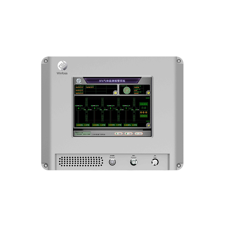
1 | SF6 Infrared Leakage Monitoring and Alarm System (host) | only | 1 | SF6 gas, O2, temperature and humidity values can be displayed on the same screen to realize alarm setting, output, historical data query, timing fan setting, remote fan control, etc. Due to the problems related to the main control room system upgrade, the equipment must obtain the computer software copyright registration certificate issued by the National Copyright Administration. And obtain the software test report of the software evaluation institution at the provincial/municipal level or above, and the SF6 integrated online monitoring system shall obtain the software product certificate in 2018. Party B shall provide the corresponding utility model or appearance patent certificate or patent acceptance notice to prove that Party B's products have independent intellectual property rights. |
2 | 2-in-1 transmitter with display (SF6, O2) | only | 12 | Must be a 2-in-1 transmitter - quantitative detection (accuracy up to 1ppm) |
3 | 4-in-1 transmitter with display (SF6, O2, temperature, humidity) | only | 4 | Must be a 4-in-1 transmitter - quantitative detection (accuracy up to 1ppm) |
4 | Output module | only | 1 | Monitoring system alarm output |
5 | Remote transmission module | only | 4 | Monitoring system alarm output |
6 | Fan controller | only | 1 | A set of front and back doors, there are staff into the automatic start of the fan |
7 | Human body infrared voice alarm device (including alarm light) | Set of | 2 | |
8 | Four-core shielded 0.75 cable | meter | 1500 | |
8 | Accessories (brackets, bolts, expansion bolts, screws, etc.) | batch | 1 |
3.2.2 Operation and control requirements
The SF6 leakage monitoring system of 500kV switching station in Tingzikou of Jialingjiang River adopts a number of new high-sensitivity four-in-one (SF6, O2, temperature, humidity) transmitters. When the indoor SF6 concentration changes slightly, the sensor can immediately respond to these changes, even if the SF6 concentration is less than 1ppmv, it can also effectively monitor. The concentration change monitored by the transmitter is converted into A 485 communication digital signal through A/D module, 485 communication module and MCU control, and the signal is sent to the main controller through the on-site RS-485 bus, which is processed and stored by the main controller, and determines whether to alarm, start the fan and remote communication and other functions, and communicates with the switch station monitoring system. The indoor SF6 concentration is effectively monitored to improve the safety of GIS equipment operation, especially to ensure the personal safety of daily patrol and maintenance personnel.
3.2.3 Composition and structure of the control device
The SF6 leakage monitoring system of 500kV switching station in Tingzikou of Jialing River is proposed to adopt 1 host +16 detection points +2 fan controllers +2 sets of human infrared and alarm lights +1 set of voice system
3.2.4 Function Requirements
1.1 SF6 gas concentration detection function
The system detects each detection point, displays the SF6 concentration value of each collection point in real time, when the SF6 gas concentration reaches 1000ppm (or preset value), the display data also prompts the exceeded information, the system makes alarm processing, sound and light alarm, automatically start the fan, remote output alarm signal, etc.
1.2 Oxygen concentration detection function
The host LCD screen displays the oxygen concentration value of each collection point in real time. When the concentration is lower than 18% (or user set), the display data will prompt oxygen alarm information at the same time. The system will make alarm processing, sound and light alarm, automatic start of the fan, remote output alarm signal, etc.
1.3 Temperature and humidity measurement function
The system can display the temperature and humidity of the room in real time. When the temperature exceeds the set alarm value, the fan automatically starts until the temperature drops back to the normal temperature. The system can also provide multi-channel temperature measurement and control function for temperature monitoring in transformer room.
1.4 Automatic control of the fan
(1) If the SF6 gas content in the environment exceeds the standard, the fan will start automatically until the alarm is lifted;
(2) When the oxygen in the environment is lower than 18.0% (or user set), the fan will be automatically started until the oxygen returns to normal;
(3) When the indoor temperature and humidity are higher than the set temperature and humidity value, the fan will be automatically started. When the temperature and humidity are lower than the alarm value, the fan will automatically stop.
1.5 Periodic exhaust function
The system can set the scheduled start time and scheduled shutdown time of the fan every day. 12 periods can be set every day. The scheduled start time and shutdown time can be set by the host.
1.6 Manual Forced Exhaust function
When the fan is closed, press the "Manual start fan" button, the fan will start immediately, and the ventilation will stop automatically after 15 minutes. If you want to stop the fan immediately, press the "strong close fan" button.
1.7 Display the last start and shutdown time of the fan
The current status of the fan can be displayed on the LCD screen, and the starting condition prompt, if the fan is in the starting state, the start time of the fan is displayed, if the fan is in the off state, the start and stop time of the last fan is displayed, which can facilitate the staff to determine whether to force ventilation before entering the switch room.
1.8 Automatic voice prompt and alarm function
(1) When the staff is near the switch room, the system automatically prompts the indoor gas detection result;
(2) When SF6 gas leakage exceeds the alarm point, the system will automatically alarm with sound and light, and stop after the alarm is eliminated;
(3) When the oxygen measurement value is lower than 18% (or user Settings), the system automatically carries out sound and light alarm, and stops after the alarm is eliminated;
1.9 Infrared detection function
The use of imported human infrared sensor, its stable operation, no error reporting phenomenon, when the staff close to the switch room door 3m range, automatically open the fan, ventilation 15 minutes after the automatic stop.
1.10 Host alarm record storage and query functions
The host has the function of automatic storage of alarm information, and the information saved has the alarm time, alarm value and alarm time. By clicking the "alarm query" on the host to view the alarm, more than 10,000 records can be stored on the alarm record. The system automatically overwrites the record after the storage is full, the query has a variety of ways to query, convenient for users to use, the current screen is the last alarm information.
1.11 Remote Data Transmission (Optional)
The host is embedded with TCP/IP protocol and RS485 communication module, (can also be transmitted to the user monitoring system through 4~20mA, this function needs to be customized), through TCP/IP protocol or RS485 can be connected to the background monitoring software, check the online operating status of the monitoring system, and can also realize the start and stop of the remote control fan. Realize the telemetry, remote communication and remote control of environmental gas detection, the software has the function of record and query, record, through the software can query the site environmental data, fan start and stop time and historical alarm data.
1.12 Self-check function
The system self-checks each sensor, and displays prompt information if there is an anomaly, so as to facilitate user maintenance and inspection.
1.13 After the LCD screen protection function is finished for 10 minutes (the duration can also be set by the user), the LCD backlight will be turned off; The LCD backlight is automatically turned on when there is a human operator.
1.14 Automatic temperature control of transformer room
The system can monitor the temperature of up to 3 main transformer chambers (36 temperature collection points) and automatically start and stop the fan of the upper and lower tuyere of the main transformer chamber.

 EN
EN



 上一条:
上一条: 

 沪公网安备31011802003762
