专注于SF6气体检测的专业化

SF6 leakage online monitoring and alarm device on-site installation should pay attention to what?
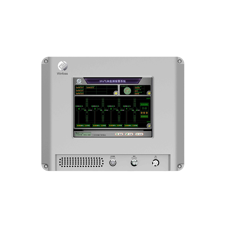
The SF6 Online Leakage monitoring and alarm instrument (WINFOSS-S1P) is composed of the monitoring host (including sound and light alarm device, human infrared voice sensor and touch display screen), SF6 and oxygen monitoring unit, temperature and humidity monitoring unit, fan control device, communication cable and host power cable, and background software. The monitoring host is connected to the monitoring unit through cables. The SF6 monitoring unit is equipped with foreign advanced infrared sensors. The system can measure SF6 gas concentration, oxygen concentration, environmental temperature, humidity and other related parameters in the switch room environment in real time, realize real-time display and communication and data exchange with the monitoring host. If an abnormal environment is detected, an alarm is sent and the ventilation device is linked. To ensure personal safety and normal operation of equipment in the switch room environment.
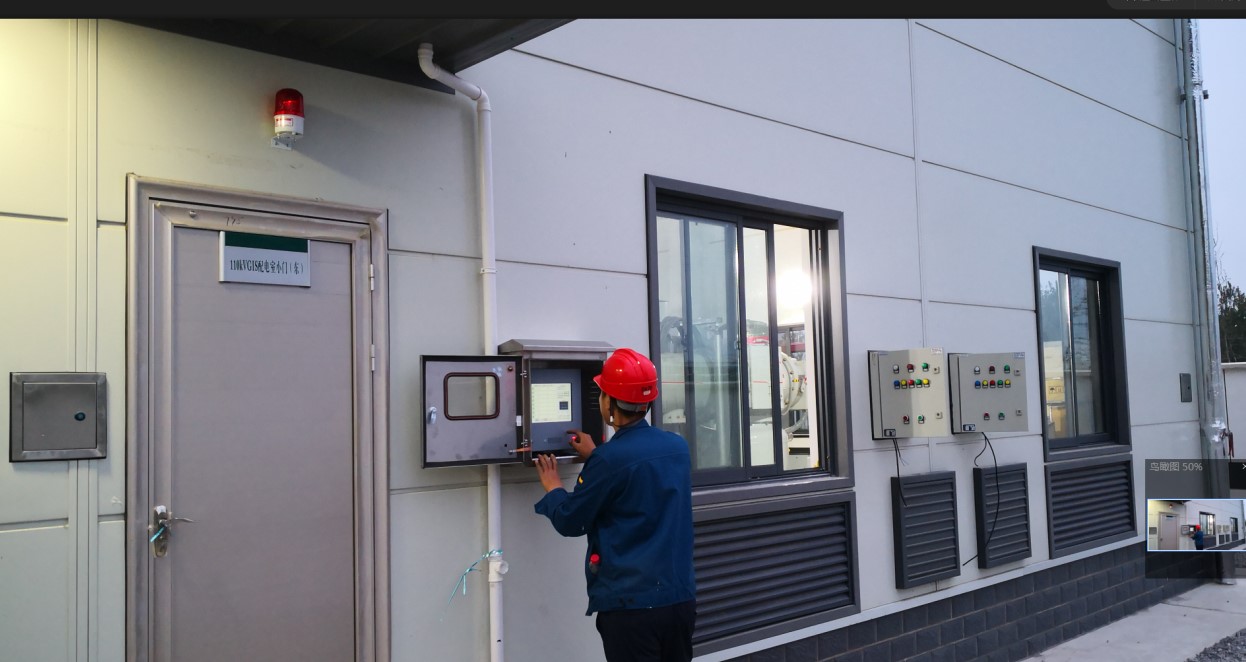
1. Monitor the installation position of the host
1). Installation position: The monitoring host is installed at the entrance of the GIS switch room according to the requirements of the State Grid, so that field staff can view the indoor test data before entering. Other entrances can be prompted by warning lights or LED screens if required by users.
2). Installation height: the center position of the touch LCD screen is level with the line of sight of the 170cm person. That is, the distance between the bottom of the host and the ground is 130-140cm. When there are other devices or distribution boxes around, follow the principle that the upper or lower edge of the main machine is flush with the upper or lower edge of other devices to avoid uneven appearance and damage to the scene.
3). Horizontal standard: there are two hanging holes on the back of the host. When installing the pendant, it is necessary to use a meter ruler to measure the connection between the two points to be drilled and the ground, that is, the two holes are the same height from the ground. At the same time, to ensure that the Angle of the hook tongue is consistent, the level of the host can be monitored by adjusting the size of the Angle.
4). Input and outlet cable specifications: If the embedded pipe does not reach the installation position of the host, it can be connected through a metal hose. Generally, all lines cannot access the host through one hole, so that the strong and weak current classification can be achieved.
5). Treatment of the main machine inlet hole: The clearance of the main machine inlet hole or other empty inlet hole shall be sealed with fireproof mud at the end (the clearance of any position caused by installation shall be treated accordingly).
Monitor installation
1) Installation position: It should be fixed in the center position below the GIS/SF6 switch, and generally adsorbed on the I-steel. If it is a cabinet switch/trolley switch, it is installed on the wall opposite the switch cabinet door (the wall with the fan). It is about 100mm above the ground.
2) Installation distribution: GIS switches are generally installed at a single interval corresponding to 1 SF6 and oxygen detection unit, cabinet switch/trolley switch, then install 1 detection unit in the middle position of every 4 cabinet switches. The T/H detection unit is generally installed in the central position of the switch room, and one is near the SF6 and oxygen detection unit, and the system has only one T/H detection unit, its number is defined as 0. If two T/H detection units are configured in the system, one should be installed in each switch room. If they are in the same switch room, they should be installed at the first and last sides of the switch room respectively.
3) : The wiring end of the installation direction monitor faces down. It is not recommended to install the monitor horizontally. It is forbidden to install the terminal facing up or facing both sides, in principle, it is not allowed to place this way, because for a long time, the terminal is easy to accumulate dust on the short circuit and other faults.
4). Fixing of the detection unit: When installing with magnet adsorption, two magnetic strips are indispensable. When fixed with self-tapping screws, both screw holes should be fixed in principle (using expansion rubber plugs). Do not use double-sided tape or epoxy resin for adhesive fixation. The number of a probe unit ranges from 02 near the entrance to the farthest position to the maximum number to meet the maintenance habits of users. And post and confirm that the detection unit number of the corresponding address does not appear confused and missing, and the location of each detection unit should be strictly unified.

 EN
EN




 上一条:
上一条: 

 沪公网安备31011802003762
